Made to order / Planning guide
Out-of-Plumb Shower Walls: What to Confirm Before Releasing a Custom Door Drawing
Equal opening widths do not prove walls are plumb. Learn what to record and verify before approving a drawing for a custom shower enclosure.
By AimeShower · Published · Updated
A measured opening width does not, by itself, establish whether a custom shower enclosure will fit. The drawing also needs to describe the finished surfaces, the direction of wall deviation and how the proposed enclosure connects to those surfaces. Equal widths at several heights can even occur between two walls that lean in the same direction.
This guide explains how to turn that uncertainty into a reviewable measurement record. It focuses on a straight opening viewed in the intended enclosure plane. Corners, curved layouts and other geometry require their own survey and configuration review.
If you already have a survey record, use the drawing-release checklist to identify whether the next step is to remeasure, obtain configuration evidence or review a changed drawing.
1. Establish what the measurement represents
“The opening is 900 mm” leaves several questions unanswered. Was that measured before tiling or between finished faces? At which height? Along the proposed enclosure line, or elsewhere across the shower? Is it a horizontal distance, or a tape measurement taken at an angle?
For a useful record, identify:
The proposed enclosure plane and which side is shown in the sketch.
The finished surfaces that define the opening, including any surfaces still to be completed.
A common height datum and the heights where readings were taken.
A vertical reference, the direction used for positive deviation, and how each wall was checked against that reference.
Units, measurement method, date, person responsible and drawing reference.
These labels make the numbers interpretable. A width measured at one depth cannot automatically describe the wall where the enclosure will actually be fixed. Likewise, measuring equal distances from a line that is itself tilted does not establish verticality.
Published installation documents illustrate why separate checks matter. KOHLER’s 1246188-2-E instructions state a wall-plumb condition separately from the opening measurements. That is a requirement for the listed KOHLER models, not an adjustment allowance for AimeShower products. S1 — page 1, wall-plumb note; page 2, “Measure the Opening”
2. Equal widths can conceal two leaning walls
Consider the simplified front-view example below. Let z be height above a shared datum, and let xL(z) and xR(z) be horizontal positions of the left and right boundaries, measured from one fixed vertical reference in the same plane.
The horizontal separation is:
W(z) = xR(z) − xL(z)
The following numbers are deliberately chosen for a geometry illustration. They are not site measurements, product dimensions, acceptable tolerances or a glass-cutting schedule.
| Height z (mm) | Left boundary xL (mm) | Right boundary xR (mm) | Separation W (mm) |
|---|---|---|---|
| 0 | 0 | 900 | 900 |
| 1,000 | 4 | 904 | 900 |
| 2,000 | 8 | 908 | 900 |
Each width is 900 mm. Yet both boundaries shift 8 mm to the right over the illustrated height. The shared movement cancels when one coordinate is subtracted from the other. The widths reveal separation; they do not reveal the individual walls’ alignment to a vertical reference. [A1 — original geometry derivation; all inputs are hypothetical]
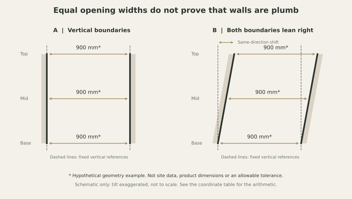
This example does not mean that every leaning opening is unsuitable. It means that a width-only record is insufficient to decide. The proposed panel geometry, wall interfaces and documented adjustment mechanisms still need to be reviewed together.
3. Record the direction of deviation, not just its magnitude
A note reading “wall out by 8 mm” is incomplete without a direction and reference. The top of a boundary might move toward the opening, away from it, or in a direction outside the front-view plane.
For the straight opening considered here, record each side independently at the relevant heights. Label the direction on the sketch and note where measurements were taken along the intended enclosure plane. Also identify local changes that the sketch does not capture, such as a bowed surface or a step in the finish.
Do not treat the three rows in the illustration as a universal survey specification. They demonstrate a mathematical point. The actual measurement locations and detail needed should be agreed with the installer and the person reviewing the proposed configuration. A few readings cannot establish that an entire surface is flat. [A2 — proposed review method and scope limitation]
Keep the reference consistent. If two people use different datums or opposite sign conventions, their readings may appear to conflict even when they describe the same surface. Resolve that before deciding that either the site or the drawing is wrong.
4. Ask what the adjustment actually changes
The word “adjustable” is not enough to approve a configuration. Ask which component moves, in which direction, and under what documented conditions.
For example, CRL’s GEN045 document describes a pivot feature that changes the door’s closing position. That specific feature should not be treated as evidence of a general wall-deviation allowance. S2 — printed page 4B-9, “Important Information,” item 1
For a custom enclosure review, use the following questions:
| Question | What must be recorded |
|---|---|
| Which component provides adjustment? | Component identification, mounting arrangement and relevant drawing or instruction revision. |
| What does the adjustment change? | Direction of movement and whether it affects closing position, an interface position or another specified feature. |
| Where are the limits documented? | The applicable supplier document or written technical confirmation for the proposed configuration. |
| What other conditions apply? | Relevant engagement, clearance, fixing and assembly requirements identified in that documentation. |
| Does it address this measured deviation? | A configuration-specific review, including any unresolved questions and the responsible reviewer. |
Do not automatically add together the advertised adjustments of several components. A combined allowance requires evidence that the adjustments can be used together in the proposed configuration. A closing-angle change, wall-interface movement and panel-height adjustment should not be treated as interchangeable quantities. [A3 — configuration-review rule; no combined capacity is claimed]
If hinge selection is part of the proposed configuration, review door weight, width, mounting and support documentation together. The hinge capacity review guide helps organize that evidence; measured wall deviation does not establish hinge capacity.
5. Keep survey dimensions separate from manufacturing dimensions
The narrowest measured opening is useful information, but it is not automatically the required glass width. A manufacturing drawing must account for the selected interfaces and components, as well as the panel geometry and assembly clearances agreed for that configuration.
Maintain three distinct records:
Survey record: what was measured, where, against which datum, and whether the surfaces were finished.
Configuration review: how the selected system is intended to accommodate that geometry, with supporting documents and open items.
Approved manufacturing drawing: the agreed dimensions and details for the identified revision, released by the responsible parties.
An annotated photograph can help locate a reading. It does not replace a labelled measurement or establish the proposed structure’s adjustment capability. Similarly, a catalogue image can identify a design direction without providing manufacturing dimensions. [A4 — proposed document-control method]
Keep the survey record and the proposed drawing revision together when preparing the project handover. The drawings and packing guide explains how to identify measurements and confirm the revision before production.
If the panel has already been manufactured and the survey does not match the approved drawing, refer the discrepancy back for technical review before attempting an installation change.
6. Decide whether to proceed, remeasure or revise
The following is a proposed review checklist, not a substitute for the project’s approval procedure.
| Finding | Next step before drawing release |
|---|---|
| Only one width is recorded, or the measured surface is unclear | Request a labelled survey showing the finished surfaces, enclosure plane and measurement locations. |
| Widths are equal, but individual wall alignment was not recorded | Request separate checks against a vertical reference. Do not infer plumb from equal widths. |
| Deviation is documented, but the proposed adjustment capability is not | Obtain the configuration-specific documentation or technical confirmation. |
| Measurements or finishes have changed since the reviewed drawing | Record the changes and reassess the affected configuration and drawing revision. |
| Inputs and applicable limits have been reconciled, with open issues closed | The named responsible parties can decide whether to release the identified drawing revision. |
Before release, the record should make it possible to answer: Who confirmed the site information, which configuration was reviewed, and which drawing revision was approved? A checked box alone does not establish technical suitability. [A5 — proposed release-review workflow]
Prepare a measurement record for your custom project
AimeShower works on non-standard, made-to-order enclosures. There is no single adjustment allowance for every design family. Provide the finished-surface sketch, the separate wall-deviation readings and any provisional dimensions so the requirements can be discussed for the proposed configuration.
The accompanying Wall Alignment Review Record keeps survey readings, component evidence and approval status separate. It is a briefing tool, not a fixed product specification or an approved manufacturing drawing.
Include the measurement record in your custom enclosure quote brief, with unresolved site dimensions marked as provisional so the quotation discussion uses the same project information.
Sources and the points they support
S1 — KOHLER, Installation and Care Instructions, 1246188-2-E. English printed/PDF pages 1–2; footer ©2017. Supports the separate wall-plumb condition and opening measurements. It does not establish AimeShower specifications. Original PDF
S2 — C.R. Laurence, GENEVA 135° Glass-to-Glass Hinge, GEN045. Printed page 4B-9; single-page PDF; footer ©2001. “Important Information,” item 1, supports only the description of the documented closing-position feature. The file is an external illustration, not a current AimeShower component specification. Original PDF
A1–A5 — editorial analysis. A1 is a disclosed hypothetical geometry example with reproducible arithmetic. A2–A5 are proposed survey and review methods derived for this article, not claims that the cited manufacturers prescribe this complete workflow. They contain no AimeShower performance data or customer results. Project-specific surveying, design and approval remain with the responsible parties.